Fox chassis cars are known for having headlight issues…everything from flashing lights when the fogs are on, to blown headlight and multi-function (turn signal) switches. Basically because all the power goes directly through those 2 switches and they can’t handle the load. So either the headlights flash or go off all together so the switch can cool down or the switch just blows. Sometimes they even melt and have been known to cause fires!
Adding relays to the mix takes the load off the switches along with providing brighter lights since power is coming directly from the battery!
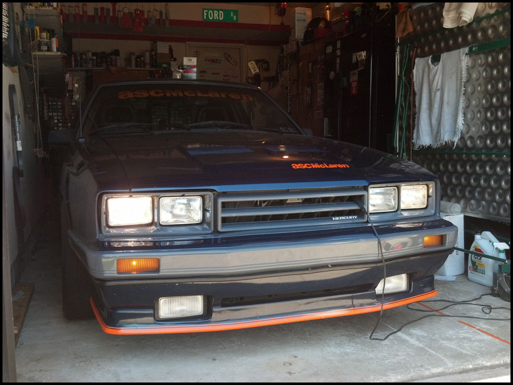
A few weeks ago I was on the way home from a show in the Capri and I realized I didn’t have any headlights. Luckily, I could hold the turn signal stalk so my bright lights worked and I was able to get home but I certainly had to fix the issue. After some research on FEP and help from other friends I figured it was either of those 2 switches. I had a spare headlight switch but that didn’t do anything – It ended up being the multi-function switch…the more expensive of the 2 but an easy fix none-the-less. However, I wanted to make sure this wouldn’t happen again so I decided to add the relays now rather than later.
You can purchase pre-made harnesses but they are expensive – the parts for the entire job are cheap, even with adding in a little bit of time it was a no-brainer for me – I love DIY projects anyway so this was a perfect project!
Again, more research on FEP pointed me in the right direction. However, with as many threads that there were over there (and elsewhere), there wasn’t anything that was super simple and stupid proof. I love wiring and am good at it but I hate dealing with wiring that I didn’t do – even if it’s factory wiring! That’s why I’m putting this together. Big thanks to BrianM over at FEP for helping me out.
The overall goal other than safer headlights was for this to be simple and easy to do and maintain if needed. A lot of guys buy factory style headlight connectors to make a 100% plug-n-play harness – and as much as I like plug-n-play I didn’t want to go that way. I didn’t like the idea of having to build a huge harness going from one side of the car to the other. Plus everything would have been “under” the car requiring me to jack it up and crawl around – that’s like work! I need something simpler! lol
I decided to tap into the stock headlight wiring that is in a harness bundle under the battery tray (NOTE – This is in my 86 Capri so the battery is on the driver’s side). Now, as far as I know, the wiring is the same for at least 86+ 5.0 and SVO cars and I’d imagine it’s the same for all 79+ fox chassis cars but don’t quote me on that. Do a bit of research to find out which wires and where you’ll need to tap into before getting started.
PARTS/TOOLS list (based on exactly how I did it):
- 2 Bosch style relays
- 2 relay sockets with pigtails and diodes – you can also make your own pigtail with push on connectors but the pre-built pigtails are SO much easier and nicer looking!
- 10 awg fuse holder (30 amp fuse)
- Misc self-tapping screws for mounting the relays
- Soldering iron (you can use butt connectors and heat shrink but I always prefer to solder wires)
- 2 lug connectors (1 for ground to chassis and 1 for power from starter solenoid
- Heat shrink
- Electrical tape
- 1 distribution stud with jumper cable (optional) – my starter solenoid was full so I needed an alternate power source. I got a distribution stud and a jumper cable made up. See below for pics/details.
First thing I did was to remove the battery and tray from the car. I located the bundle underneath and started peeling away the factory wrapping to reveal the wiring underneath.
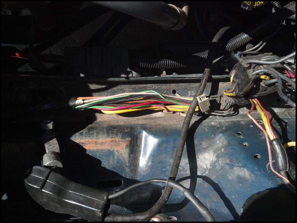
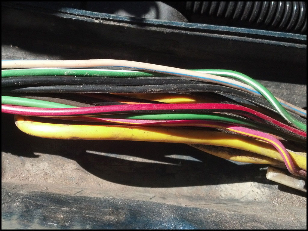
This is a close up of the wire bundle – Here you’ll notice a Red/Black wire and a Green/Black wire – these are the 2 we need. Red/Black is for the low beams, and Green/Black is for the high beams. Each wire will be associated with a different relay. Make sure to inspect the wires before proceeding…if they are frayed or hacked up you’ll need to address that first…mine were perfect.
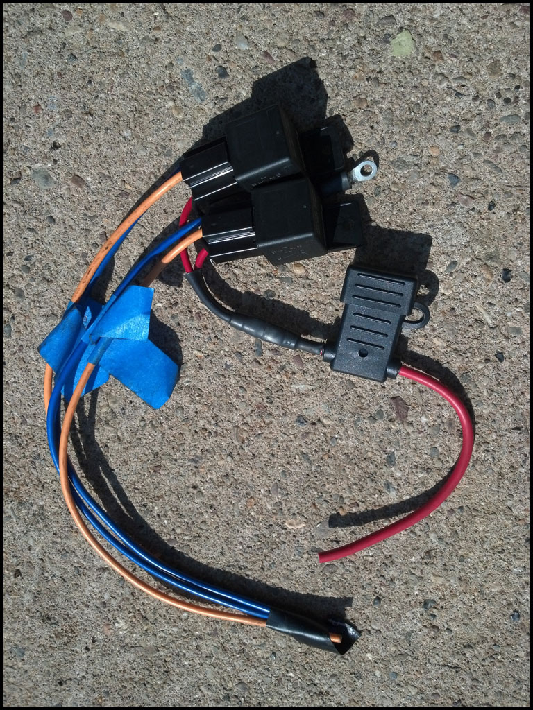
Below is the relay setup after I prepped it once I knew exactly how I wanted to mount it. I will be mounting them side-by-side just like this. I’ve joined the 2 black ground wires (or pole 85 of the relay) together with a lug connector and heat shrink. I’ve also joined the 2 red power wires (or pole 30 of the relay) together and then to the 10awg fuse holder. I cut everything to size based on where/how I wanted to mount it. Of course you’ll want to mock everything up on your car to figure out exactly where you will be mounting everything. The fuse holder will tuck in nicely just above the relays. I have the ground wire coming up between the relays. The blue and yellow wires will be going to the bundle above to wire the actual lights…more on that later.
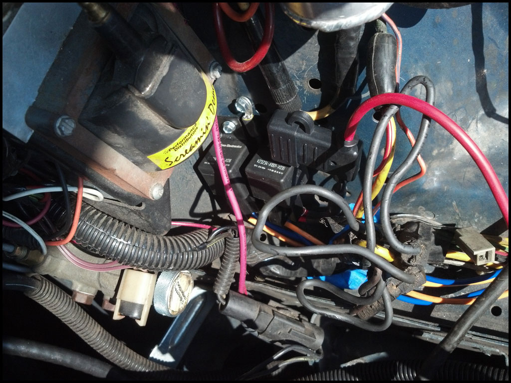
This is the entire assembly mocked-up in location. I thought this was the perfect spot. Hidden by the coil cover, dry and easily accessible if need be. Also, the standard relay pigtail is plenty long enough to reach the headlight wires so I don’t have to lengthen anything!
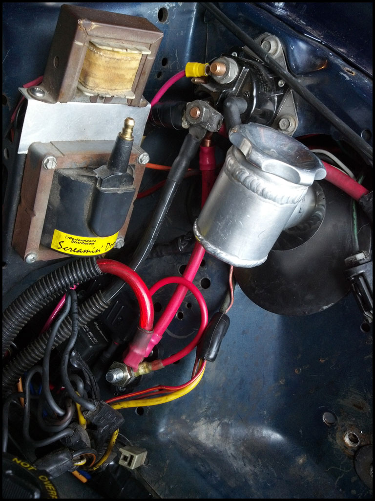
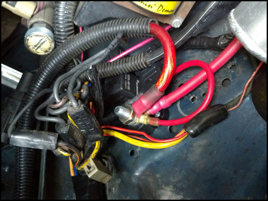
At this point it was time to mount my distribution stud. As mentioned above my starter solenoid was full so I needed another option. I had my local alternator guy make me a 7.5″ jumper wire that would go to from the starter solenoid to my new distribution stud. I first had to move my 3g alternator wire from the starter solenoid to the new distribution stud so the new jumper wire I had made would fit. The other end of the jumper wire will go on the new dist stud along with the 3g alternator and the power wire from the relays! I could have simply gone directly to the battery but I wanted a cleaner look. As mentioned this is optional and there are a bunch of other ways to accomplish the same task. Do what you like.
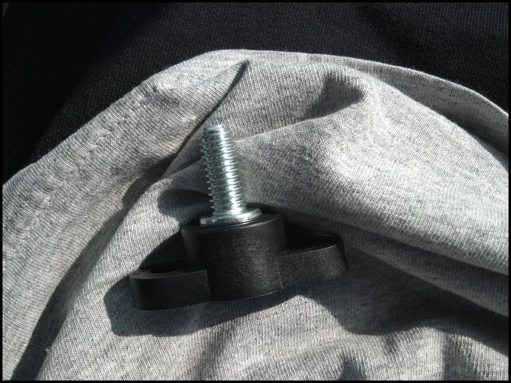
This is the distribution stud. Just a simple stud insulated around a plastic mounting base. Perfect for what I need.
Here you can see the jumper wire from the solenoid to the dist stud and how I have everything routed to the new stud.
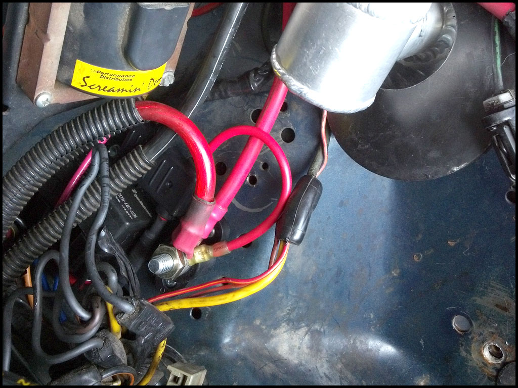
A couple close ups of the stud with everything mounted to it. Still have some room on there for a couple more things! Everything at this point is still loosely mounted. Once all my soldering is complete and I’m 100% happy with everything I will tighten permanently.
Once I was happy with how the assembly was going to mount it was time to start wiring the actual lights. As mentioned above we’ll be using the Red/Black wire (low beams), and the Green/Black wire (high beams).
Start with one wire first.
Low Beams:
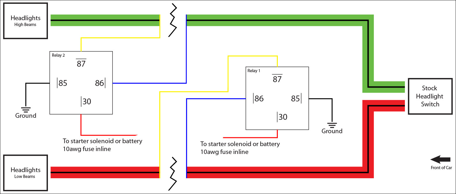
Cut the Red/Black wire. Now, connect the blue wire (or pole 86) from relay 1 to the side of the Red/Black wire that is coming from the back of the car (this actually goes to the headlight switch)…then connect the yellow wire (or pole 87) from the same relay (relay 1) to the end of the Red/Black wire going to the front of the car (actually going to the headlights).
Once they are connected, soldered and protected with heat shrink move on to the other wire…
High Beams:
Cut the Green/Black wire. Now, connect the blue wire (or pole 86) from relay 2 to side of the Green/Black wire that is coming from the back of the car (this actually goes to the headlight switch)…then connect the yellow wire (or pole 87) from the same relay (relay 2) to the end of the Green/Black wire going to the front of the car (actually going to the headlights).
Once they are connected, soldered and protected with heat shrink it’s time to start buttoning everything up.
Wiring Diagram:
This should help make sense of everything. Fully understand it before starting. It’s super simple and easy to follow. There are a million headlight relay upgrade wiring diagrams out there…even for different make/model cars but they are all very confusing IMO. I created this to be bare bones easy to read and follow.
Once I got all the soldering out of the way I double checked everything and buttoned it all up. I tucked the wires I soldered back into the harness bundle and re-taped…looks factory! You can barely see the blue and yellow wires to the right…these will be hidden once the coil cover is re-installed.
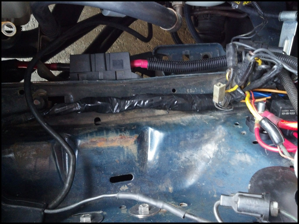
Here is a shot after everything was complete. Totally hidden.
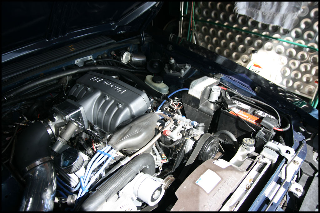
Make sure to test everything real good once complete. I had my dad drive in front me of during the day just to make sure everything was ok and that my lights stayed on! Can’t hurt to be safe.
Please feel free to contact me if you need help or want me to put together the pieces for you. Enjoy!